VOACAP Version 16.1207W propagation prediction examples
27 April, 6 May, 2021
Chuck Varney
For the examples shown in Figure 1. and Figure 2. below:
Month: July
Sunspot number: SSN:113, the 12-month running mean for July 1937
foF2 coefficients: CCIR
3 MHz man made noise at the receiving site: - 164 dBW/Hz
Power fed to the transmit antenna: 1 W (0 dBW)
Maximum gains of the transmit and receive antennas are oriented toward one another.
Example 1. Transmitter at Gardner Island (4.66S 174.54W) and receiver 10,431 km distant at
St. Petersburg, FL (27.75N 82.67W). TIGHAR (Entry 142) assumed receive frequency: 24.84 MHz
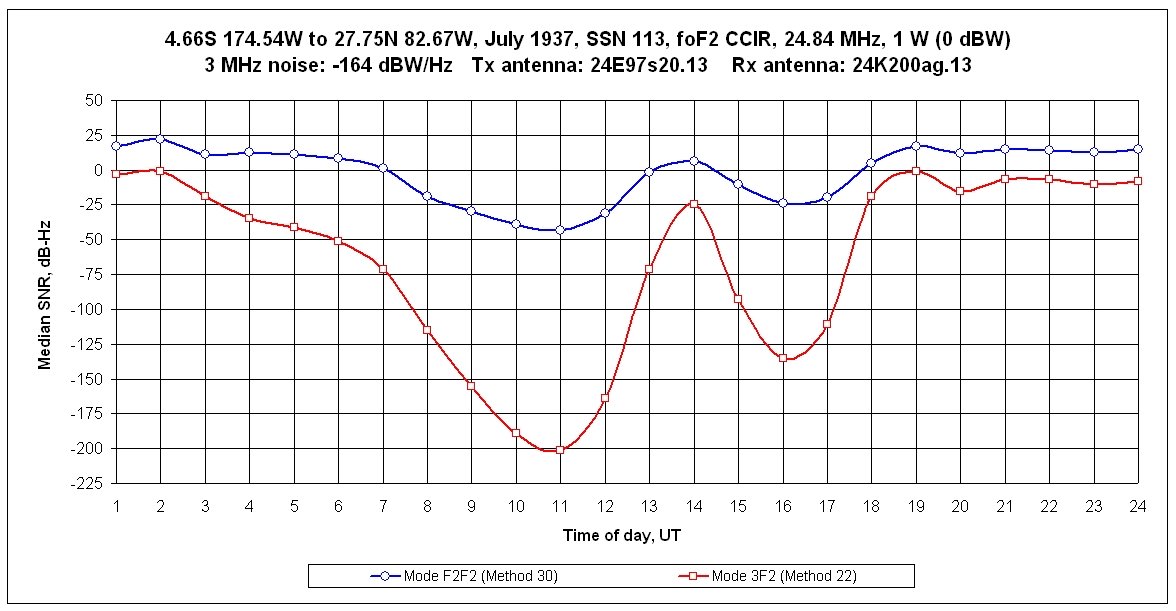
Figure 1. Gardner Island to St. Petersburg, FL - Median signal to noise-density ratio versus hour of the day for
VOACAP's smoothed short path-long path propagation model (Method 30) and a forced short path, multi-hop,
model (Method 22).
Method 30 (F2F2) run data used for Figure 1., including transmit antenna takeoff and receive antenna arrival angles and transmit and receive antenna gains. (Maximum and minimum antenna gain sums were 3.8 dBi and -9.3 dBi. No takeoff or arrival angle exceeded 15.3 degrees.)
Method 22 (3F2) run data used for Figure1., including antenna takeoff and arrival angles and transmit and receive antenna gains. (Maximum and minimum antenna gain sums were 0.3 dBi and -4.5 dBi.)

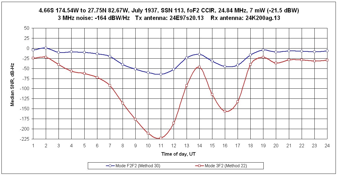
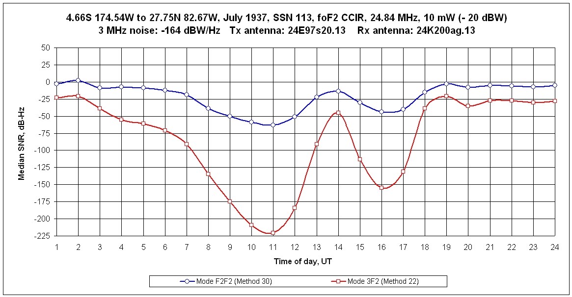
Figure 1 results with power reduced to 10 mW (rounded up from the 6.1 mW that I calculated for the 4th harmonic of
the WE 13-C transmitter tuned to 6.21 MHz with a plate output of 50 W).
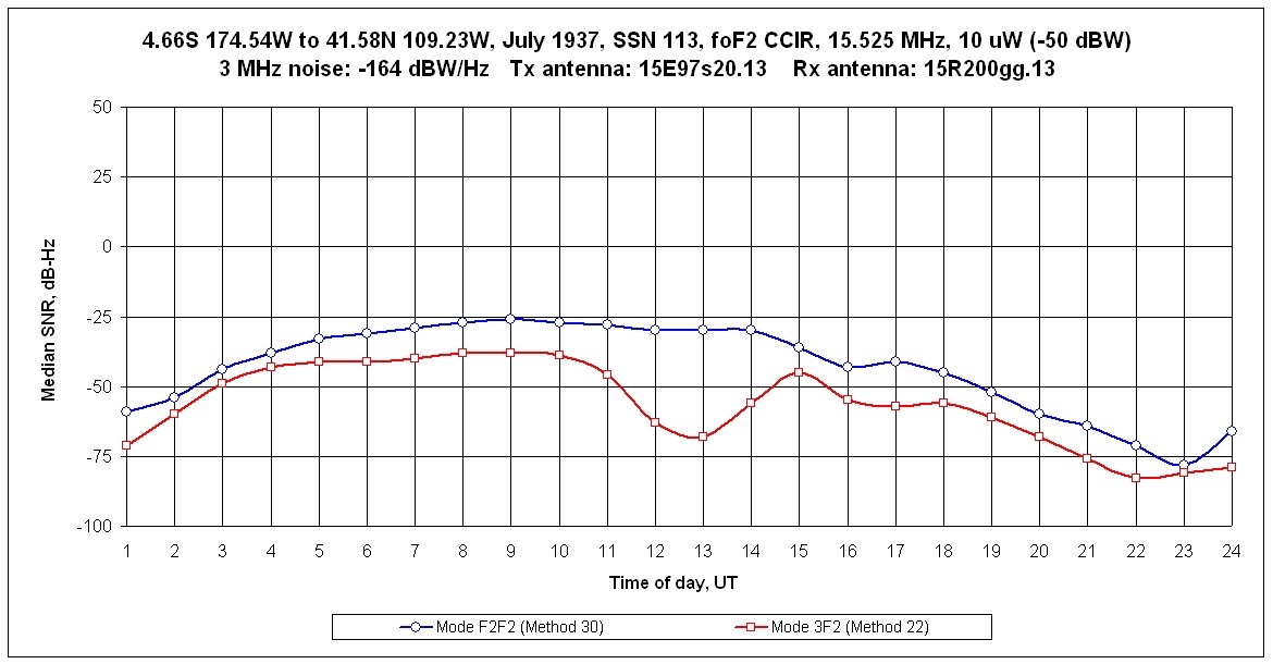
Example 2. Transmitter at Gardner Island (4.66S 174.54W) and receiver 8,347 km distant at
Rock Springs, WY (41.58N 109.23W). TIGHAR (Entry 81) assumed receive frequency: 15.525 MHz
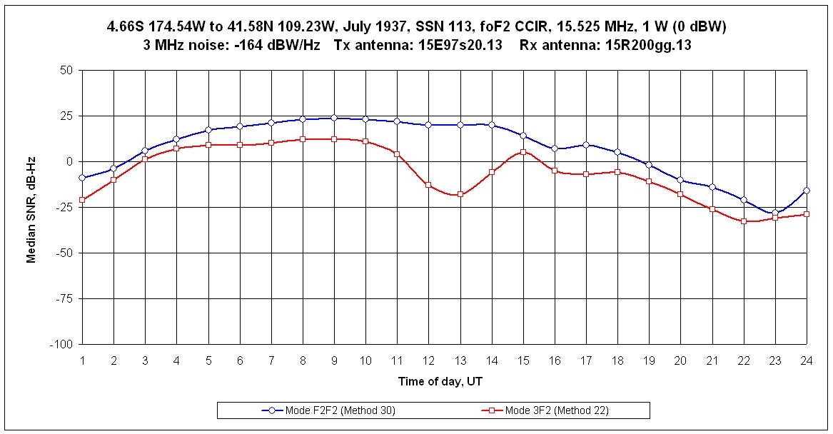
Figure 2. Gardner Island to Rock Springs, WY - Median signal to noise-density ratio versus hour of the day for
VOACAP's smoothed short path-long path propagation model (Method 30) and a forced short path.
multi-hop, model (Method 22). Method 22 gave 3F2 as the most reliable mode for 20 hours, but gave 4F2
for hours 19-22 UT.
Method 30 (F2F2) run data used for Figure 2., including antenna takeoff and arrival angles and transmit and receive antenna gains. (Maximum and minimum antenna gain sums were 5.9 dBi and -2.7 dBi. No takeoff or arrival angle exceeded 28 degrees.)
Method 22 (3F2/4F2) run data used for Figure 2., including antenna takeoff and arrival angles and transmit and receive antenna gains. (Maximum and minimum antenna gain sums were 6.9 dBi and -12.6 dBi.)

Figure 2. results with power reduced to 10 uW (rounded up from the 4.15 uW that I calculated for the 5th harmonic of the WE 13-C transmitter tuned to 3.105 MHz with a plate output of 50 W).
27 April, 6 May, 2021
Chuck Varney
For the examples shown in Figure 1. and Figure 2. below:
Month: July
Sunspot number: SSN:113, the 12-month running mean for July 1937
foF2 coefficients: CCIR
3 MHz man made noise at the receiving site: - 164 dBW/Hz
Power fed to the transmit antenna: 1 W (0 dBW)
Maximum gains of the transmit and receive antennas are oriented toward one another.
Example 1. Transmitter at Gardner Island (4.66S 174.54W) and receiver 10,431 km distant at
St. Petersburg, FL (27.75N 82.67W). TIGHAR (Entry 142) assumed receive frequency: 24.84 MHz
Figure 1. Gardner Island to St. Petersburg, FL - Median signal to noise-density ratio versus hour of the day for
VOACAP's smoothed short path-long path propagation model (Method 30) and a forced short path, multi-hop,
model (Method 22).
Method 30 (F2F2) run data used for Figure 1., including transmit antenna takeoff and receive antenna arrival angles and transmit and receive antenna gains. (Maximum and minimum antenna gain sums were 3.8 dBi and -9.3 dBi. No takeoff or arrival angle exceeded 15.3 degrees.)
Method 22 (3F2) run data used for Figure1., including antenna takeoff and arrival angles and transmit and receive antenna gains. (Maximum and minimum antenna gain sums were 0.3 dBi and -4.5 dBi.)
Figure 1 results with power reduced to 10 mW (rounded up from the 6.1 mW that I calculated for the 4th harmonic of
the WE 13-C transmitter tuned to 6.21 MHz with a plate output of 50 W).
Example 2. Transmitter at Gardner Island (4.66S 174.54W) and receiver 8,347 km distant at
Rock Springs, WY (41.58N 109.23W). TIGHAR (Entry 81) assumed receive frequency: 15.525 MHz
Figure 2. Gardner Island to Rock Springs, WY - Median signal to noise-density ratio versus hour of the day for
VOACAP's smoothed short path-long path propagation model (Method 30) and a forced short path.
multi-hop, model (Method 22). Method 22 gave 3F2 as the most reliable mode for 20 hours, but gave 4F2
for hours 19-22 UT.
Method 30 (F2F2) run data used for Figure 2., including antenna takeoff and arrival angles and transmit and receive antenna gains. (Maximum and minimum antenna gain sums were 5.9 dBi and -2.7 dBi. No takeoff or arrival angle exceeded 28 degrees.)
Method 22 (3F2/4F2) run data used for Figure 2., including antenna takeoff and arrival angles and transmit and receive antenna gains. (Maximum and minimum antenna gain sums were 6.9 dBi and -12.6 dBi.)
Figure 2. results with power reduced to 10 uW (rounded up from the 4.15 uW that I calculated for the 5th harmonic of the WE 13-C transmitter tuned to 3.105 MHz with a plate output of 50 W).